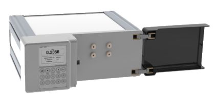
Quite often there are tasks that require chromatographic analysis of substances with different refractive indices and do not have sufficient light absorption or fluorescence. These compounds include saturated hydrocarbons, sugars, lipids, many organic acids, some detergents, and other substances. It is either impossible or difficult to analyze them using a spectrophotometric detector. If you exclude complex and expensive light scattering detectors or mass spectrometric devices, the only alternative is a differential refractometer.
Main applications of the refractometric detector
- Analysis of carbohydrate and/or organic acid content in food and beverages.
- Analysis of the composition of petroleum products (marginal hydrocarbons).
- In medical studies for the determination of protein in urine, blood serum, subretinal and other liquid media.
- In the pharmaceutical industry in the study of aqueous solutions of medicinal products.
Most modern refractometric detectors use prismatic cells made using deep optical contact (DOP) technology. This construct, despite its widespread use, creates a number of problems. Mechanically unstable cells are destroyed even with a small increase in pressure, which imposes restrictions on the speed of the eluent supply, the location of the detector and the use of devices that create back pressure. In addition, such cells require forced thermal stabilization to suppress the temperature drift of the baseline and circuits with mechanical compensation for the displacement of the output beam to adjust the zero value of the baseline.
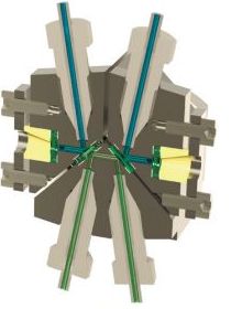
Developed for the Steyer-M line, the REF-105 refractometric detector differs from its analogues by a three-chamber cell of an original design that does not require DOP technology. This cell not only provides passive optical thermal compensation, which makes it possible to avoid temperature control in most cases, but also makes it possible to work with liquid flows up to 10 ml/min at a pressure of up to 30 bar. The cell design is protected by several Russian and international patents.
Some features of the REF-105 detector
- The design of the optical cell (birefringence) allows you to achieve a significant increase in the sensitivity of the device.
- The materials of the optical cuvette make it possible to use solvents with a pH of 0-14.
- Quick access to the operating mode, in most cases – 5-7 minutes.
- Low sensitivity to changes in external temperature.
- The minimum number of optical and mechanical elements (telescope and optical cuvette) and the minimum number of mechanical settings can improve the reliability and stability of the instrument.
- Possibility of manual and program control.
- Ability to work with third-party software via the RS-232 port.
- Ability to connect an external ADC via an analog output.
- Electronic zero setting when changing the eluent. No need for mechanical adjustment.
- Possibility of using the detector for fast chromatography.
- The possibility of polymer design of the entire liquid path for use with aggressive eluents or in those tasks where metal can cause the destruction of analytes.
- The unique parameters of the permissible operating pressure in the cell (30 bar) allow the use of devices for creating back pressure, which, in some cases, can dramatically reduce the noise and drift of the device.
- The use of a highly stable LED as a light source makes an additional contribution to improving the metrological characteristics of the detector.
- The detector can be used for analytical, preparative, and gel-penetrating chromatography.
| Light source | monochromatic LED |
| Light source wavelength, nm | 650 |
| Volume of analytical cuvette, µl | 2 |
| Maximum flow rate through the cuvette, ml / min | 10 |
| Operating pressure in the cell, bar, max | 30 |
| Dynamic range Δn (difference of refractive indices in the working cuvette and in the comparison cuvette), E.P.P. | 1·10-7 - 5·10-2 |
| Operating range of refractive index (n), E.P.P. | 1,00-1,75 |
| Detection limit (for glucose), g | 1·10-8 |
| Noise without flow in distilled water (at a time constant of 2 s), E.P.P. | 1·10-8 |
| The level of zero-signal fluctuation noise on the distilled water flow (at a time constant of 2 sec), E.P.P. | 4·10-7 |
| Zero signal drift on distilled water flow, E.P.P./h | 5·10-4 |
| Automatic optical thermal stabilization due to the three-channel cell design | yes |
| Eluent pH range, pH units | 0 - 14 |
| Remote update of the microprocessor software | yes |
| Interfaces | Aquilon BUS, RS-232, USB, analog output |
| Time to enter the operating mode, min | 10 |
| Power supply, voltage/frequency | (110-240 V)/ 50 Hz |
| Power consumption, VA, max | 20 |

 The radiation of the LED 1 is collected by the condenser 2 in a narrow parallel beam of light incident on the front face of the cuvette at an angle of 90°. The diaphragm 3 cuts out a strip of light from the circular section of the beam with a direction that coincides with the direction of the axis of the channels 4’, 4’’, 4’’’, flow cell 4.
In the case where the same chromatographic eluent is present in all flow channels, the light passing through channel 4’ is refracted on the large side of the channel at an angle that depends on the refractive indices at the eluent/cuvette material interface. Again refracting in the opposite direction at the same angle in a strong channel 4’’ hits the next plane-parallel plate, and according to the same rules of refraction, passes the channel 4’’’.
Regardless of the refractive index of the chromatographic eluent used and the temperature of the liquid, in accordance with the superposition principle, the direction of light at the outlet of the flow cell remains on the same optical axis as the direction of light at the entrance of the cell.
The two-site photodiode 5 is installed at a certain distance from the output face of the flow cell 4 perpendicular to the optical axis. The position of the photodiode is chosen in such a way that the energy of incident light is equally distributed on both photosensitive sites. If the photodiode is switched on according to the differential circuit, the measured output current is zero. Thus, regardless of the temperature conditions surrounding the detector or the change in the eluent, the baseline remains stable.
When the components of the analyte pass through only one of the channels, the direction of light at the cuvette outlet deviates from the direction of the main optical axis by an angle proportional to the change in the refractive index in this channel. The energy equilibrium at the photosensitive sites of the photodiode 5 is disturbed proportionally to the change in the angle of deviation from the optical axis of the detector, and accordingly, the measured current from the photodiode also changes proportionally.


